


This system comprises a precision tool holder and a corresponding coated carbide broaching insert, engineered as an integrated solution for internal broaching operations on CNC lathes and machining centers. The assembly is designed to produce keyways, splines, hexagonal profiles, and other non-circular internal forms with high dimensional accuracy and repeatability.
Tool Holder Specifications & Design
Material: Manufactured from alloy tool steel, with the insert pocket and support surfaces induction-hardened to HRC 52–60 for resistance against deformation and abrasive wear.
Clamping Interface: Available with cylindrical shanks, VDI flanges, or Morse tapers to suit various machine turrets and spindles. Flatted shank designs are provided for positive anti-rotation locking.
Insert Seating: Precision-ground pocket with locating surfaces accurate to ±0.02 mm, ensuring repeatable insert positioning upon indexing or replacement.
Coolant Delivery: Internal through-tool coolant channels direct fluid directly to the cutting edge, reducing thermal load and improving chip evacuation from blind holes.
Clamping Mechanism: Utilizes a top-clamp screw or wedge system to securely lock the insert, capable of withstanding axial pulling forces up to the holder's rated capacity.
Coated Carbide Insert Specifications
Substrate: Micro-grain tungsten carbide (ISO grade K20–K40 or equivalent), selected for high transverse rupture strength and resistance to chipping under interrupted cutting conditions.
Coating: Multi-layer PVD (Physical Vapor Deposition) coating, typically TiAlN or AlCrN-based, with a total thickness of 2–4 µm. This provides:
High hot hardness for elevated cutting temperatures.
Low coefficient of friction to reduce built-up edge formation.
Oxidation resistance up to approximately 800–900°C.
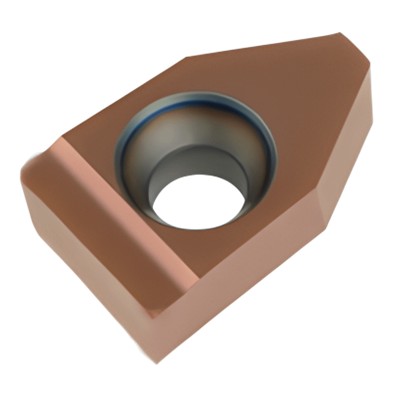
Insert Geometry: Ground peripheral edges with defined positive or negative rake angles, depending on the profile being cut. Chip-breaker features are integrated into the face geometry to control chip flow and prevent packing in the bore.
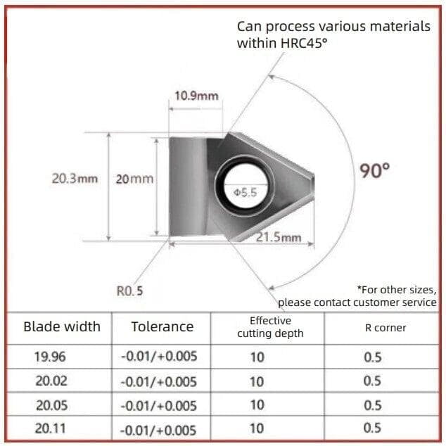
Dimensions: Manufactured to ISO or custom tolerances to match the holder pocket precisely, with cutting widths ranging from 2 mm to 40 mm and cutting lengths up to 50 mm per pass, depending on insert size.
Operational Technical Data
Cutting Speed Range: 20–80 m/min for steel alloys; 40–120 m/min for cast iron and non-ferrous materials, subject to insert grade and coating selection.
Feed per Stroke: 0.005–0.03 mm per cutting edge, determined by workpiece material and desired surface finish.
Maximum Stroke Length: Defined by the holder design and machine Z-axis travel, with progressive depth increments typically limited to 0.1–0.3 mm per pass to prevent insert overload.
Profile Tolerances: Capable of maintaining keyway width tolerances of IT7–IT9 and surface roughness values down to Ra 1.6 µm under stable machining conditions.
System Integration Notes
The holder and insert are dimensionally matched such that the insert's cutting edge lies precisely on the tool centerline or at the programmed offset. The holder's rigidity, combined with the insert's wear-resistant coating, allows for consistent form accuracy over multiple machining cycles, with insert life primarily governed by total cutting length and workpiece hardness. Indexing or replacement is performed without disturbing the holder's setup in the machine, preserving datum references.
Customize